-
A function built into the
custom QSAVE function.
It requires the drawing to have the border sheet attached or inserted in Pspace
and a separate title fill-in block named CDMTTBAT or CUSTTBAT inserted also.
When CDMNDX is executed the drawing is zoomed by window to the drawing extents. This is to ensure all floating viewports are visible. The custom view number is recorded with the view area for each floating viewport. The drawing is zoomed to its previous condition. The block CDMTTBAT is examined and the title attributes are concatenated into a single title string and recorded with the drawing name and the sheet number.
The text file CDMNDX.TXT located in the current drawing directory is opened and modified. If the current drawing already has an entry in the file it is updated with the new information, otherwise a new entry is added for the drawing. The information is keyed to the drawing name so if the name changes an additional entry will be made. Use notepad to arrange the entries in order, delete obsolete entries, and to insert dummy entries for section headings. The order is never changed by CDMNDX. The entries are made in the order the sheets are QSAVE'd. Manual edits to the order of drawings in CDMNDX.TXT will always remain as edited. Sheet number, sheet title, and viewport information is automatically overwritten for a drawing when it is QSAVE'd.
-
SHTNDX
-
a custom command that will generate a sheet index
exactly matching the sheet numbers and titles in the project. That is unless
the custom QSAVE function containing the CDMNDX function is not used.
-
Generates rectangles of all viewports of every sheet
in the project and sheet number text in the center of the rectangle. Typical
uses: create layout sheets, key maps or location maps; display viewport
boundaries for edits to xref'd profiles. Use ESBND
to erase all such rectangles and text.
-
Zooms to the specified view of any sheet, including
the dview twist, while in any drawing. Great for finding any sheet's viewport
area while in an Xref associated with it.
-
Auto-Break STRing – Wrap a string of text at a
specified number of characters. Creates multiple lines of text.
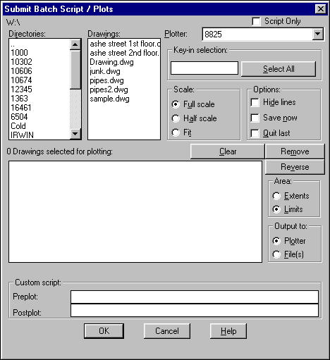
Batch PLOT - Creates and runs a script file on one or a multitude of drawings. The drawings can be from different directories or even from different drives. Script may optionally exclude plotting instructions. This allows the creation of a batch script for any purpose.
The plotter list is constructed from *.ppf files (plotter parameter files) found in AutoCAD's search paths by the program. At least one *.ppf file is required. See the instructions for creating a PPF file below.
Browse in directories and select drawings to include in the batch. Wildcard entries in the "Key-in selection" edit box or use the "Select all" button.
The "Scale" selection:Operates in conjunction with dimscale in each drawing. Dimscale=0 is
read as 1:1
Fit will fit the specified area (limits or extents) onto a 24"x36"
plot.
The "Options" toggles:
Hide lines - Pspace hidden line removal.
Save now - Save the current drawing before running the script.
Quit last - Quit AutoCAD when the batch is complete.
Output is directed to either the plotter or to files.
Any valid custom script can be entered in the preplot
or postplot lines provided. If a large amount of script is needed it can
be saved in a separate script file and called using a special format on
the lines provided. To call an external script to be added before or after
a plot for each drawing, type all in lowercase and without the quotes or
brackets:
"filename <script filename including extension>"
Check the "Script only" box to eliminate all plot related script entry.
How to create a PPF file:PPF files are text files containing the specific script input required for a given plotter. They contain two or three lines depending upon the required entry.
The first line contains all of the input required after "PLOT" and "Limits" or "Extents" and before "Write the plot to a file?". The answer to "Write the plot to a file?" is automatically provided.
The second line contains all of the input required following this and preceding: "Enter the Size or <width>,<height>"; "Rotate plot clockwise 0/90/180/270 degrees"; and, "Remove hidden lines?" All answers to these are automatically provided.
The third line contains all of the input required (if any) following "Remove hidden lines?"
Every entry must be separated by a space and make sure no space is at the end of a line.
The best method to determine these for any plotter is to cause AutoCAD to step through plotting at the command line. This is done by entering (COMMAND ".PLOT") at the command line. Write down every question and the response that you want bplot to give. Always begin with option 5, detailed plot configuration.
BPLOT can be configured for any plotter in this manner.-
Optionally:
Break a string of text: Delete left end of text to put it above; Delete right end of text to put it below; or
Add a line of text above or below the selected text.
-
Contour elevation labeling tool. Reads contour elevation
and formats text and places it on the contour. Use HDTEXT to hide contour
under the label.
-
Copy entities from xrefs into the current drawing.
For example, survey text is often rotated or upside down and not the desired
height. Rather than retyping to annotate a sheet, copy it using CPL and
use the text tools (pop-up menu) to modify height, rotation, and alignment.
-
Customized DTEXT routine. Automatically sets layers
and colors based on user specified text height.
-
Edit anything that appears to be text, attributes
in blocks, dimensions, and text. Text that is within a block cannot be edited
unless the block is exploded.
-
Sanitary/Storm Sewer Design – Design and draw
alignment plan and profile.
Command-Line functions available within GPDGN.
-
Glue STRing – Join multiple strings of text.
All adopt properties of first string.
-
Creates 3Dfaces under the CMUD title block. This
feature is used in conjunction with Hideplot to automatically blank out
the drawing under the title block when plotted. Use VSTAT
to check and set the status of Hideplot in viewports.
3Dfaces cannot be seen unless the AutoCAD variable SPLFRAME is on (1). Note: This variable is primarily used to enable or disable display of spline frames. Leaving it on could produce undesirable results if the drawing contains splines. The commands SON and SOF will turn NPLT layers on and off respectively. Frozen layers will not be processed by hidden line removal (hideplot on). Do not freeze NPLT layers. Use EHDT to erase all HDTEXT 3Dfaces.
-
Creates 3Dfaces under all or selected text in the specified space and optionally
creates 3Dfaces under all or selected text in dimension entities also. This
feature is used in conjunction with Hideplot to automatically blank out
the drawing under text when it is plotted. Use VSTAT
to check and set the status of Hideplot in viewports.
3Dfaces are placed on layers matching the text layers but with NPLTHS added to the layer name. 3Dfaces cannot be seen unless the AutoCAD variable SPLFRAME is on (1). Note: This variable is primarily used to enable or disable display of spline frames. Leaving it on could produce undesirable results if the drawing contains splines. The commands SON and SOF will turn NPLT layers on and off respectively. Frozen layers will not be processed by hidden line removal (hideplot on). Do not freeze NPLT layers. Use EHDT to erase all HDTEXT 3Dfaces.
-
ISOlate ViewPort layers – Uses vplayer and the custom view number to
freeze in the current viewport all layers created for other viewports.
-
Places a standard arrowhead (LT=line terminator) at the nearest end of a
line or heavy polyline.
-
Places CMUD north arrow. Reads viewport scale to determine symbol scale.
-
Multi-line text and leader. Automatically incorporates the custom view number
into text and leader layers.
-
Modifies integers and real numbers. Add, subtract and/or change decimal
precision. Operates on the first number in a text string (subsequent numbers
are unchanged). When decimal precision is increased zeros are added. When
decimal precision is decreased the original number is rounded.
-
Modifies station numbers (numbers with "+" in them). Add, subtract
and/or change decimal precision. Operates on the first station in a text
string (subsequent stations are unchanged). When decimal precision is increased
zeros are added. When decimal precision is decreased the original station
is rounded.
-
Available Project Listing – Project Access Dialog. Use PROJ to locate
projects, explore project folders, and open project drawings.
-
Use INSERT to place this property number symbol (block). Contains attribute
for property number and 3DFace to hide lines under symbol.
-
Stamp, Index, Save and Backup drawing. This function is critical to the
operation of several other custom tools that rely on the index file it creates
and maintains through CDMNDX
.
-
Copy multiple attributes and text from blocks in xrefs, e.g. property labels.
Realigns notes vertically and horizontally either under the first string
or in a new location.
-
Move or copy multi-line text and leaders. Optionally adds northing and easting
below existing text. Automatically incorporates the custom view number into
text and leader layers.
-
Realigns notes vertically and horizontally either under the first string
or in a new location. All text adopts the properties of the first string.
-
Places CMUD standard box around TBM notes. Puts 3DFace under it to hide
lines. Select the middle line of the standard 3-line TBM note.
-
Standardizes text rotation to CDM standard rotation angle break point of
17 degrees past vertical. Accounts for dview twist when reading text angles.
-
Restore saved layer ON, OFF, FREEZE, THAW settings to current drawing. Layer
settings must have been saved using XRLAYERS
. These two tools preserve and quickly restore the significant effort of
setting layer properties. RXRLAY can be used with BPLOT
to transfer layer settings to all P&P sheets of a project.
-
Generates rectangles of all viewports of every sheet in the project and
sheet number text in the center of the rectangle. Typical uses: create layout
sheets, key maps or location maps; display viewport boundaries for edits
to xref'd profiles. Use ESBND to erase all
such rectangles and text. Requires CDMNDX.TXT created and maintained by
custom QSAVE using CDMNDX
-
Typical Notes catalog and placement tool. Typical notes, multi-line formatting,
and bubble with fill-in information are all stored here for rapid recall
and placement.
-
Line labeling tool for plan views. Reads line layer, formats text and places
it on the utility line. Use HDTEXT
to hide lines under the label.
-
Automatically position a profile in a viewport and update station and elevation
text. Requires block with station and elevation attributes. Block is CPP40SPL
(for multiples of 1:20 scale) or CPP50SPL (for remaining multiples of 1:10
scale). Snap lower left viewport corner to grid index line intersection.
Snap right viewport boundary to a vertical grid index line. Left and right
viewport boundaries are match lines if necessary.
-
Zooms to the specified view of any sheet, including the dview twist, while
in any drawing. Great for finding any sheet's viewport area while in an
Xref associated with it. Requires CDMNDX.TXT created and maintained by custom
QSAVE using CDMNDX
-
Reports current viewport status of: Hideplot; Scale (zoom factor); Viewtwist
(Dview); and Layer name. Prompts to keep hideplot on, but it can be turned
off.
-
Xref overlay macro. Overlays the specified xref at insertion point (0,0,0),
rotation angle=0, and scale=1.
-
Save layer ON, OFF, FREEZE, THAW settings of current drawing. Layer settings
can be restored using RXRLAY
. These two tools preserve and quickly restore the significant effort of
setting layer properties. RXRLAY
can be used with BPLOT to
transfer layer settings to all P&P sheets of a project.
-
Xref edit tool. Use this when entities in an xref must be edited. Select
an entity in the xref to open. XRSWAP offers to save the current drawing,
opens the xref to edit, and zooms the view to match the original drawing.
Use XRSWAP again when the edits are complete to automatically go back to
the original drawing.
Most of GPDGN's features are utilized from within its multi-level dialog interface. The following features are custom commands available within AutoCAD if GPDGN has been loaded.
Design Element - Plan Tools
SYMSTA
-
(GPDGN) Inserts the specified block at
the specified station.
-
(GPDGN) Brings the specified data point
to view center via ZOOM CENTER.
-
(GPDGN) Brings the specified plan station
to view center via ZOOM CENTER.
Design Element - Profile Tools
CASEPIPE
-
(GPDGN) Creates casing pipe in plan or
profile view. Also used to create anti-seep collars.
-
(GPDGN) Automatically increments anti-seep
collar stations by specified amount for rapid multiple entry. Otherwise
set to 0.
-
(GPDGN) Fragments (inserts points in) lines
longer than specified distance. Use to prep pressure pipelines to follow
grade in parametric design.
-
(GPDGN) Annotate plan features in profile
by station key-in or pick in plan.
-
(GPDGN) Brings the specified profile station
to view center via ZOOM CENTER.
Sheet Element - Plan Tools
MLGEN
-
(GPDGN) Creates match line text and a 3DFACE
at the specified station. Specify Left or Right, (the match lines are
drawn as part of the alignment using GPDGN's Match Line feature and the
DRAW button).
-
(GPDGN) Add/Replace station labels along
alignment.
Design Tools
ALNDMP
-
(GPDGN) Dumps the alignment data to the
text screen.
-
(GPDGN) Displays the current alignment
name at the command line.
-
(GPDGN) Calculates and writes trench depths,
lengths and a summary to files:
<align filename>.tdf = table; and
<align filename>.txt = summary
-
(GPDGN) Removes duplicate manhole data
from the current alignment.
-
(GPDGN) Displays station and offset of
the point. Points near data points and not perpendicular to the alignment
display data point station and distance.
-
(GPDGN) List of commands within GPDGN.
-
(GPDGN) Display a text screen listing of
Seq#, Sta and ID of points with matching IDs.
-
(GPDGN) Reinitializes GPDGN, **WARNING**
wipes the current alignment from memory. Has no effect on alignment files
saved to a drive.
-
(GPDGN) Set default increment for Match
Line Stations - Global Edits.
-
(GPDGN) Resequence manhole ID numbers (replaces
previous ID's, uses range settings).
-
(GPDGN) Swaps the current alignment data
with the previously loaded alignment.
-
(GPDGN) Adds Z coordinate of zero or sets
Z coordinate to zero (save fails if Z=0 is not present).
Project Constants
-
Project Constants are those informational items in a title block that are
the same for every sheet in a document set. They are to be put in the project
title block drawing which is xref'd to each sheet. This guarantees consistency
and ease of editing regardless of the total number of sheets in the project.
-
These individual labels are best handled as a group. They can all be copied
from the xref using CPL and modified together after they are all copied.
Make their justification Middle Center, then adjust their height and rotation
globally using text tools (pop-up menu)