|
NOTICE! ParaPIPE draws pipe and fittings using size parameters in an external data file named PIPEFIT.DAT. Although every effort has been made within PIPEFIT.DAT to faithfully tabulate the dimensions of pipe and fittings contained in the American Pipe Manual, ParaCADD shall not be responsible for the correctness and accuracy of the data contained in PIPEFIT.DAT. If you discover errors or omissions in PIPEFIT.DAT please kindly bring them to our attention. ParaPIPE is provided AS-IS and without warranty of any kind. Unlicensed use of ParaPIPE is expressly forbidden. Use of ParaPIPE is confirmation of your agreement to the following:
Licensed users may edit PIPEFIT.DAT. To aid such users in managing their data the Excel spreadsheet named PIPEFIT.XLS is provided on the licensed product CD. |
| Set Size(s) first! | |
|
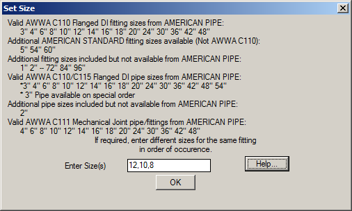 All sizes shown may be used for all connection types except Mechanical Joint. Mechanical Joint pipe and fitting sizes are restricted exclusively to the MJ sizes listed in the American Pipe Manual. It is always the user's responsibility to determine if any particular pipe or fitting size, material, and connection type is actually available and appropriate. |
| Set Connection Type | |
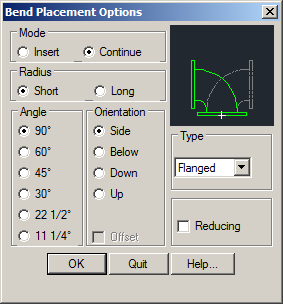
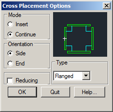
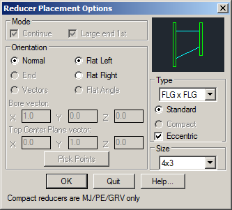
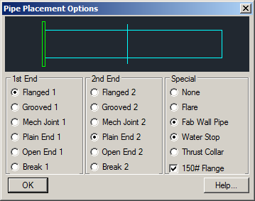
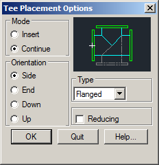
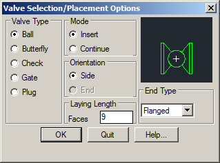
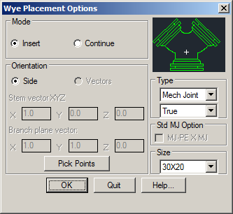
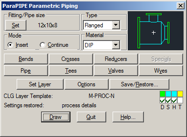
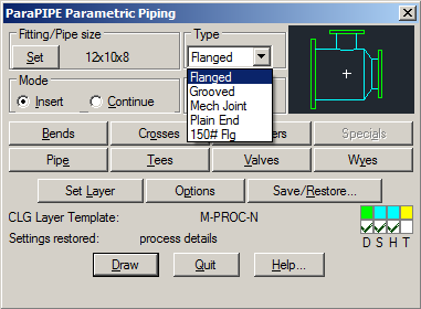
The type of connection for all fittings is set from the "Type" menus found on this main dialog and all of the fitting options dialogs (except for reducers and pipe). Reducers and Pipe both allow setting a separate connection type for each end which are independent of the setting for all other fittings. These settings must be made from the Pipe and Reducers options dialogs. |
 |
| Set Material | |
|
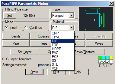
The material for all fittings is set from the "Material" menu found on this main dialog. The material setting is only used within "Data Tag" objects created in conjunction with the drawing of pipe and fittings. Data tags are only created when the "Draw creates: Data Tag" toggle is checked in the Drawing and Display Options dialog. |
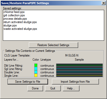
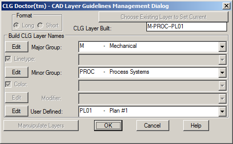
| Set Base Layer and Status | |
User settings made from this dialog control color, linetype, and base layers used in drawing pipe and fittings. |
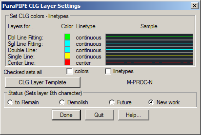
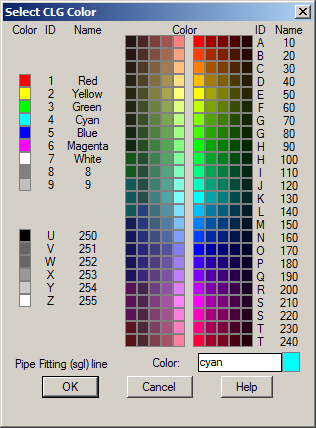
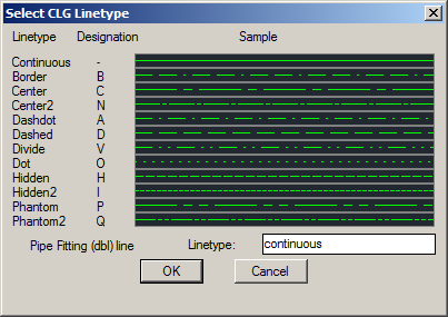
Status selection determines the single last character of the CLG Base Layer which divides pipe and fittings into four (4) groups; "existing to remain", "existing to be demolished", "future", and "new work". See the Drawing and Display Options dialog for display control by status. Each of the color and linetype swatches can be double-clicked to set them. |
| Drawing and Display Options. | |
Several display tools and drawing options are available in this dialog. "Display Scale" allows the user to automatically filter ParaPIPE's layers to display only the appropriate representation of each size in the piping design for a selected scale. If the double-line wall separation would be less than 1/8" plotted at the selected scale then the single-line representation is shown. Otherwise, the double-line representation is shown. "Draw creates:" tells ParaPIPE what to include when drawing pipe and fittings. For example, when creating a detail that will always be plotted at just one scale there may be no need for both single-line and double-line representations, or hiding solids, or tag data. Check only the features needed; however, it is always easier to turn off unnecessary feature layers than it is to recreate those features later. When in doubt instruct ParaPIPE to create ALL features. |
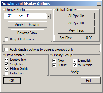
The "View Tags" button toggles the ATTDISP system variable between "Normal" and "On". Tags, where the user has elected to create them, are invisible attributes within the blocks "ATTFIT" and "ATTPIPE". It may be necessary to regen to see them after ATTDISP is set to "On". "Display Group" provides layer on/off filtering based on the status the user selects in the CLG Layer Settings dialog |
|
Hiding objects are used in conjunction with the current elevation and hidden line removal. If some pipe and fittings are drawn using a higher elevation than others and hiding objects were created with them then hidden line removal will cause all piping and other linework drawn crossing them at a lower elevation to be hidden at plot time. Hidden line removal for floating viewports is a viewport property. Use the mview command to set it. Hidden line removal in paper space is a plot dialog setting. The DRAWORDER command may also be used to affect the appearance of any objects either above or below others. |
|